Lightplane Renderer
Renderer module API
The Lightplane Renderer operator is implemented via following interfaces:
PyTorch module:
LightplaneRendererFunctional interface:
lightplane_renderer
Visit Lightplane Renderer API reference for detailed documentation.
EA rendering with MLP decoding
Lightplane Renderer implements the Emission-Absorption (EA) method which marches along rendering rays in order to image a 3D feature grid (represented with a grid-list grid).
It outputs the final color c, alpha value m and expected ray-termination length r of each ray’s pixel, as follows:
Sample
N=num_samplesequispaced 3D pointspt_3d_ibetween thenearandfarray-lengths:pt_3d_1, ..., pt_3d_N = origin + t * direction, t = linspace(near, far, num_samples)
Using Lightplane’s MLP decoder, each sampled point
pt_3d_iis annotated with opacity valueo_iand color vectorc_i(of an arbitrary dimension). Here opacityo_i = softplus(ro_i)is a softplus-activated raw opacityro_i, andc_i = sigmoid(lc_i)is output by a sigmoid activation of predicted color logitslc_i.The architecture of the decoder depends on the value of
use_separate_color_gridargument ofLightplaneRenderer:LightplaneRenderer.use_separate_color_grid==Falsegrid -> f_i -> trunk_mlp -> e_i -> e_i + ray_encoding -> color_mlp -> c_i -> opacity_mlp -> o_i
An MLP
trunk_mlpmaps the grid-sampled featuref_ito a trunk featuree_i, which is later converted to opacity and color with a pair of additional color and opacity MLP headscolor_mlpandopacity_mlp. The trunk featuree_iis summed withray_encodingbeforecolor_mlpto make the predicted color viewpoint dependent.LightplaneRenderer.use_separate_color_grid==Truegrid -> f_i -> opacity_mlp -> o_i color_grid -> cf_i -> cf_i + ray_encoding -> color_mlp -> c_i
The lightplane kernel receives a pair of opacity and color grid-lists
gridandcolor_grid. Each grid-list is sampled yielding featuresf_iandcf_irespectively, followed by a grid-specific MLP (opacity_mlp,color_mlp) converting the sampled feature to opacity and color. The color featurecf_iis summed withray_encodingbeforecolor_mlpto make the predicted color viewpoint dependent.
The list of colors and opacities predicted for each point along the ray is integrated to form the final color render
c(real vector), ray-length renderr(scalar in[0, inf]), and alpha valuem(scalar in[0, 1]):
c = sum_[i=0 ... N] (T_(i-1) - T_i) * c_i  # color render
r = sum_[i=0 ... N] (T_(i-1) - T_i) * delta_i  # ray-length render
m = 1 - T_N  # alpha value
T_i = exp[-(gain * delta_0 * o_0 + ... + gain * delta_i o_i)]  # transmittance
where delta_i is the distance between two adjacent samples along the ray, and T_i is the Transmittance of i-th point.
Renderer configuration
Scaffolded rendering
Lightplane allows to use a binary voxel-grid scaffold to fast-track raymarching for ray-points that are known to be unoccupied (i.e. they have 0 opacity o_i==0).
If the scaffolded raymarching is enabled, the renderer will first sample the binary scaffold voxel grid using nearest neighbor interpolation.
For a non-zero scaffold indicator, the renderer will proceed with MLP-decoding the sampled feature to opacity and color.
If the scaffold indicator yields zero, the renderer will skip MLP-decoding and directly output 0 opacity and color for the point.
Note
Scaffolded ray-marching is enabled by setting the scaffold argument of LightplaneRenderer.forward to a
binary (B, D, H, W) tensor.
Opacity noise injection
To prevent the renderering decoder from collapsing to predicting zero opacities everywhere, the renderer also supports random opacity noise injection.
If enabled, the opacity o_i = softplus(ro_i + n_i); n_i ~ N(0, inject_noise_sigma) is redefined to softplus-activate the predicted raw opacity jittered with a noise vector eps sampled from a zero-centered Gaussian with variance inject_noise_sigma.
Note
Opacity noise injection is enabled by setting the inject_noise_sigma argument of LightplaneRenderer to a value bigger than 0. Reproducible rendering passes can be achieved by setting the seed inject_noise_sigma of the random noise to an integer.
Modeling background
The default Lightplane renderer only represents points lying inside the [-1,1] NDC cube which can be limiting for unbounded outdoor scenes where representing distant background is important.
To help representing the background, Lightplane supports two important tools: a) Disparity-space background ray-point sampling b) Coordinate contraction
Disparity-space background ray-point sampling
In order to render distant parts of the scene, inspired by NeRF++, Lightplane supports sampling of ray points beyond the far plane with disparity spacing.
More specifically, Delta_i defines the sample spacing of between the i-th and i+1-th 3d point far_pt_3d_i beyond sampled beyond its ray’s far ray-length as:
Delta_i = far / ((i + 1) * (disparity_at_inf - 1) / num_samples_inf + 1)
Here, num_samples_inf corresponds to the total number of background ray-points and disparity_at_inf is a small constant defining the disparity of the last sample along the ray.
For illustration, the following plots the ray-length r_i = sum(delta_0, ..., delta_N, Delta_0, ..., Delta_i) as a function of the index i of the point along the ray:
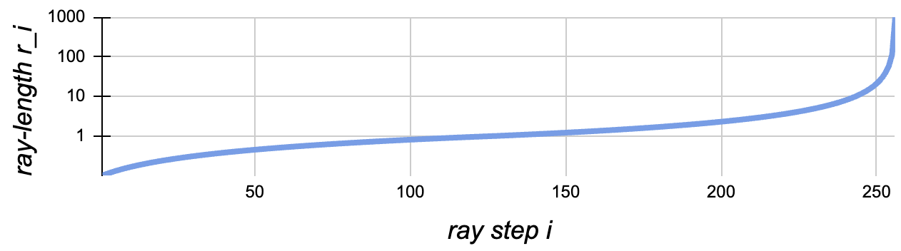
For the following settings: num_samples = num_samples_inf = 128, disparity_at_inf = 0.001, near = 0.1, far = 1.0.
Note
The disparity-space sampling is enabled by setting num_samples_inf in LightplaneRenderer to an integer value > 0.
Coordinate contraction
Disparity-space sampling alone is inefficient for modelling distant space because the grid-list represents only the space within the [-1,1] cube.
To deal with the latter, following MERF, we allow the box-based coordinate contraction function which ensures that any finite 3D point pt_3d lands lands within the [-1, 1] cube:
                     0.5 * pt_3d[k]                                   if |pt_3d|_inf <= 1
contract(pt_3d)[k] = 0.5 * pt_3d[k] / |pt_3d|_inf                     if pt_3d[k] != |pt_3d|_inf > 1
                     0.5 * (2 - 1/pt_3d[k]) pt_3d[k] / |pt_3d[k]|     if pt_3d[k] = |pt_3d|_inf > 1
where k in [0, 1, 2] is the coordinate index.
When coordinate contraction is enabled, it is applied to the ray-point before just before sampling features from the grid-list:
pt_3d = contract(origin + t * direction)
Note
Coordinate contraction is enabled by setting contract_coords in LightplaneRenderer to True